Reference
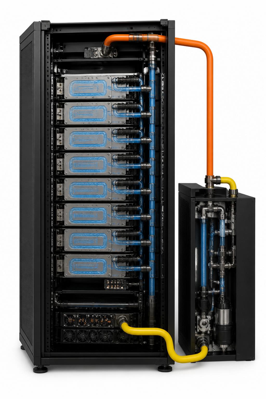
Anatomy of a liquid-cooled AI loop.
From facility water to silicon die — every interface that matters, with the temperatures, components, and failure modes we plan for.
- 0118–32°C
Facility supply
Treated water from the chiller plant or dry cooler delivered to the data hall through insulated risers.
- 0232–45°C
CDU primary loop
Coolant distribution unit exchanges heat between facility water and the closed secondary loop. Pumps, filters, and pressure control live here.
- 0340–45°C
Manifold supply
Brass or stainless manifolds distribute warm coolant to each rack via vertical drops with isolation valves.
- 04—
Quick-disconnect
Dripless blind-mate QDs let racks hot-swap without coolant loss. The single most failure-prone joint in the loop.
- 0545 → 55°C
Cold plate
Microchannel plates clamped to GPU and CPU dies. 1–2L/min per plate, pulling 700–1200W per device.
- 0654–58°C
Return manifold
Heated return collects from all racks and feeds back to the CDU — and increasingly into heat-reuse loops.
Flow schematic
Two loops, one heat path.
ΔT 10°C secondary · 5–8 m³/h per CDU · N+1 pump redundancy
Need immediate hydronic support?
Critical leak response, pump diagnostics, and pressure stabilization. Engineers en route in under 4 hours.